TM 55-1520-240-23-9
11-42
RIG COCKPIT CONTROL ASSEMBLIES
(Continued)
11-42
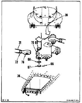
53.
Working through left access (36) turn rod end
(76) of link (71) until link can be positioned in
bellcrank (70) with bolt (69) installed loosely.
54.
Torque nut (72) of link (71) to 103 inch-pounds.
55.
Install bolt (69), washer (68), and nut (67) in
bellcrank (70).
56.
Torque nut (67) to 30 to 45 inch-pounds. Install
cotter pin (66).
57.
Check bolt (69). Bolt shall not rotate with torque
less than 10 inch-pounds. There shall be no
axial looseness. If bolt rotates or is loose, add
washer under nut and repeat step (56).
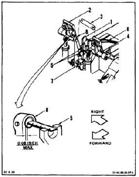
INSPECT
NEUTRAL ALIGNMENT CHECK
58.
Working in cockpit, slide pin (3) out of pilot’s
pedal tube (8). Press lever (1) and position right
pedal (2) forward. Release lever.
59.
Remove pin (3) from tube (4).
60.
Press lever (1). Pull pedal (2) aft to center
adjustment hole (7). Release lever.
61.
Check position of pedal tubes (4 and 8).
Measure tube positions from lugs (5) of fixture
(6). Distance must not be more than 0.06 inch
forward or aft. If distance is not more, go to step
62. If distance is more, repeat steps 1 thru 18,
then steps 58 thru 61.
11-172