TM 55-1520-240-23-9
11-276
ASSEMBLE AFCS COMPUTER UNIT (CONTROL BOX) (AVIM)
(Continued)
11-276
9.
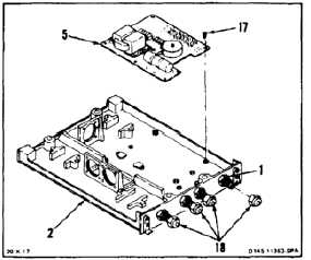
Position base circuit board (5) in base (2) and
install eight screws (17). Use sealant (E345) on
screws.
10.
Install four caps (18) on fittings (1).
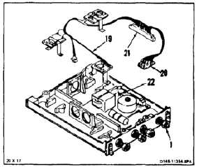
Connector must be installed correctly.
Serious damage can occur if
connector is incorrectly installed.
11.
Position wire harness (19) with board (20)
towards fittings (1). Install connector (21) on
base circuit board pins (22).
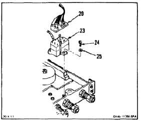
12.
Install accelerometer (23) as follows:
a.
Position accelerometer (23) on base (2).
b.
Install three screws (24) and washers (25).
Use sealant (E345) on screws.
c.
Install connector board (20).
d.
Install braided tape (E403) around
accelerometer (23) and connector board (20).
Apply adhesive (E62) to knots of braided
tape. Wear gloves (E186).
11-1061