TM 55-1520-240-23-7
9-124.1
LIGHT LEAK TEST
(Continued)
9-124.1
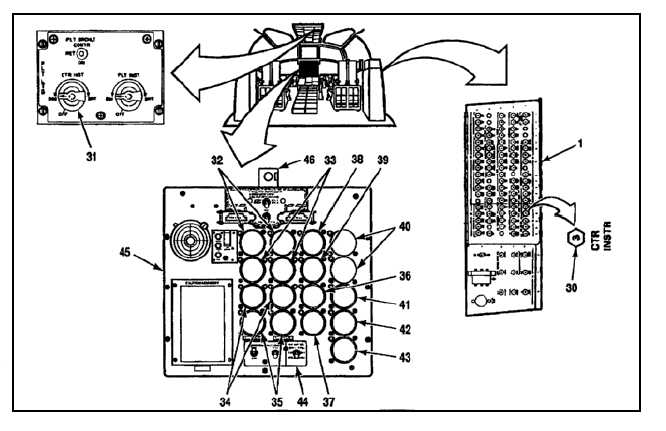
CENTER INSTRUMENT PANEL LIGHTS
23.
While performing steps 24 through 26, check
lighting. There shall be no white light leaks from
NVG blue/green lighting.
24.
Close CTR INSTR LIGHTING circuit breaker (30)
in No. 2 PDP (1).
25.
Turn CTR INST control (31) to BRT. Check the
following lights. Brightness shall increase evenly
as control is turned, and light color shall be
blue/green.
a.
Two Gas Generator Tachometers (32)
postlights.
b.
Four Power Turbine Inlet Temperature
indicators (33) postlights.
c.
Four Engine Oil Temperature Indicators (34)
postlights.
d.
Two Engine Oil Pressure Indictors (35)
postlights.
e.
XMSN Oil Temperature Indicator (36)
postlight.
f.
XMSN Oil Temperature Seletor Switch (37)
postlight.
g.
XMSN Oil Pressure Indicator (38) postlight.
h.
XMSN Oil Pressure Selector Switch (39)
postlight.
i.
Two Cyclic Trim Indicators (40) postlights.
j.
Fuel Flow Indicator (41) postlight.
k.
Fuel Quantity Indicator (42) postlight.
l.
Fuel Quantity Selector Switch (43) postlight.
m.
Caution Panel/VHF Antenna Select Panel
(44) lightplate.
n.
Fire Emergency Warning Panel (45)
Lightplate.
o.
Two Standby Compass (46) postlights.
26.
Turn control (31) to OFF. Check instrument
panel lights of step 25. They shall decrease in
brightness as control is turned. When control is
at OFF, panel lights shall be off.
27.
Open circuit breaker (30) of No. 2 PDP (1).
9-481