TM 55-1520-240-23-7
9-25.2
REPAIR AND TEST BATTERY CABLE (AVIM)
(Continued)
9-25.2
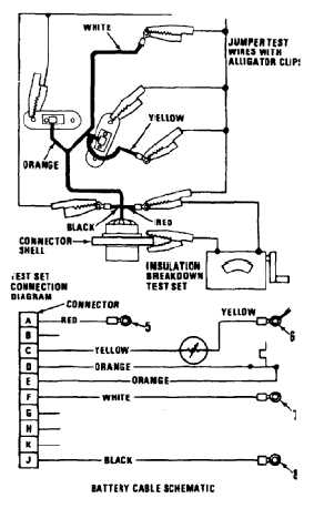
5.
Connect cable assembly to insulation breakdown
test set. Use jumper wires to connect all
terminals and temperature devices together.
6.
Operate test set. Refer to TM 11-6625-273-12.
Resistance measurement must not be below
500,000 ohms. Discard battery cable that does
not meet this requirement.
7.
Check continuity of battery cable with a
multimeter. Connect multimeter. Connect
multimeter leads to connector pins and terminals
as indicated and measure resistance value.
Discard battery cable if values are not as shown.
NO BREAK - WORK HARDER
Connector Pin
To
Connector
Pin or
Terminal
Resistance
Pin A
Terminal (5)
0 to 0.5 ohms
Pin C
Terminal (6)
See note
Pin D
Pin E
0 to 0.5 ohms
Pin F
Terminal (7)
0 to 0.5 ohms
Pin J
Terminal (8)
0 to 0.5 ohms
NOTE
At 50ºF, resistance should be 1600
to 2400 ohms. At 75ºF, resistance
should be 800 to 1200 ohms. At
100ºF, resistance should be 400 to
600 ohms.
9-73