TM 55-1520-240-23-7
8-80.5.1
TEST AND ADJUST FUEL QUANTITY INDICATOR USING PSD 60-1AF FUEL QUANTITY
TEST SET
(Continued)
8-80.5.1
PART II. CALIBRATION OF DIGITAL TOTAL FUEL
QUANTITY INDICATION
1.
Read and observe all safety precautions listed
above.
2.
Ground aircraft to earth ground per approved
procedure.
3.
Open Left and Right Forward and Aft Fuel Tank
access panels.
4.
Disconnect the following connectors from the fuel
tank access panels 114PS518.
TANK
HARNESS#
TANK
CONN#
RIGHT MAIN
300W7
057W2
LEFT MAIN
300W6
057W9
FWD RT AUX
300W4
057W1
FWD LT AUX
300W2
057W10
AFT RT AUX
300W5
057W5
AFT LT AUX
300W3
057W6
5.
Verify that the following breakers are closed:
CIRCUIT BREAKER
PDP #
CAUTION PANEL
No. 1
XFMR RECT
No. 1
REV CUR CO
No. 1
FUEL QTY
No. 1
FUEL QTY XFEED
CONTROL
No. 1
REFUEL
No. 1
6.
Connect fuel quantity tester CHASSIS jack (J-7)
to airframe ground between the Right Main and
Right Forward Aux fuel tanks located at STA 210.
7.
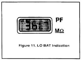
Lift latches to unlock tester. Turn ON-OFF switch
to ON. If words "LO BAT" appear in upper left
corner of LCD display (Figure 11), replace
batteries.
8.
Allow a 3 minute warm up before using tester
to measure cable.
9.
Connect PSDAF-106 "T" cable "MAIN & AUX
HIZ" lead to TANK UNITS HIZ terminal (J-5) on
tester (Figure 1).
10.
Connect PSDAF-106 "T" cable "MAIN LOZ" lead
(Figure 10) to tester TANK UNITS LOZ terminal
(J-4) (Figure 1).
11.
Rotate tester FUNCT switch (S-2) to MEASURE
EXT.
12.
Rotate tester SELECT switch (S-3) to the TU.
13.
Read and record cable LOZ-HIZ capacitance
displayed on LCD. If capacitance exceeds .5 pf,
repair or replace interface cable.
14.
Disconnect cable MAIN & AUX HIZ and MAIN
LOZ leads from tester TANK UNITS terminals.
15.
Connect MAIN & AUX HIZ lead to INDICATOR
HIZ terminal (J-2) on tester (Figure 1).
16.
Connect MAIN LOZ lead to INDICATOR LOZ
terminal (J-1) on tester (Figure 1).
8-239


