TM 55-1520-240-23-7
9-153.1
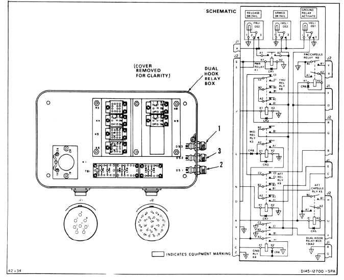
TEST DUAL HOOK RELAY BOX (AVIM)
(Continued)
9-153.1
6.
Remove 28 vdc from L of J2 only and apply to
C of J2.
a.
There shall be 28 vdc across J2-b(+) and
J1-B(-).
b.
There shall be continuity between J1-B and
J2-a.
7.
Apply ground to G of J1. There shall be continuity
between G and D of J1 and indicator light DS1
(2) shall come on.
8.
Apply 28 vdc to E of J2. Indicator light DS2 (3)
shall come on.
9.
Press three lights (1, 2, and 3). Lights shall
come on.
10.
Apply 28 vdc to A and ground to V of J2. Apply
and remove ground to U of J2. There shall be
continuity between W and U of J2.
11.
Apply and remove ground to X of J2. There shall
be continuity between X and Y of J2.
12.
Remove all power connections.
FOLLOW-ON MAINTENANCE:
None
END OF TASK
9-626