TM 55-1520-240-23-6
7-135
UTILITY HYDRAULIC SYSTEM
(Continued)
7-135
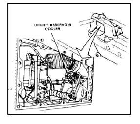
Reservoir/Cooler
A reservoir/cooler module is located in the pylon area on
the right side. The reservoir section of the module stores
fluid for system operation. The cooler is mounted on top
of the reservoir. It is connected by flexible ducting to a
fan that is activated by a thermal switch in the cooler.
Sensors in the unit send information on fluid temperature
to the maintenance panel in the ramp area. An LVDT in
the reservoir provides indication of the system fluid level
to the maintenance panel.
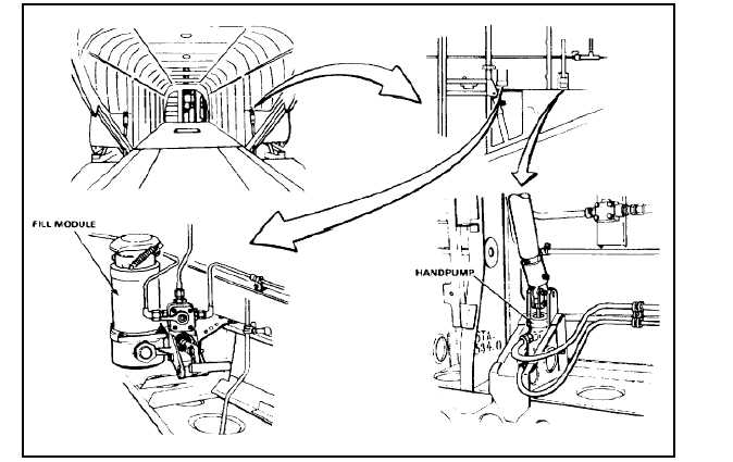
Fill Module
Hydraulic fluid is added to the system through a fill
module at the right side of the cabin in the ramp area.
The same module is used to fill the utility system and
both of the flight control hydraulic systems. Selection
of the system to be serviced is by a rotary valve in the
module. All hydraulic systems may be serviced either
static or while system is operating. Fluid added to the
reservoir is pulled through the module and delivered to
the return module and reservoir/cooler by operating a
small handpump on the module.
Handpump
The handpump is a two-stage manually operated pump
located on the right side of the cabin at sta. 527. It is
primarily used to pressurize the APU start accumulator
to start the APU. In an emergency, it can also be used to
pressurize the cargo ramp and door. In an emergency it
can be used to pressurize the utility subsystems.
7-610