TM 55-1520-240-23-6
7-132
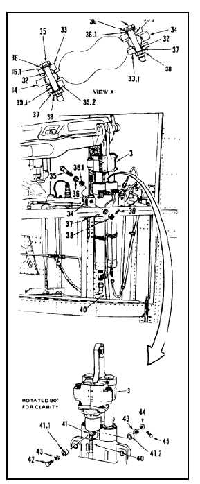
INSTALL AFT PIVOTING SERVOCYLINDER
(Continued)
7-132
Make sure bushings are installed in
lugs. Otherwise, personal injury, loss
of life, or loss of helicopter can result.
12.
Check that flanged bushings (32) are installed
in forward inboard lug (33) and aft outboard lug
(33.1).
13.
Have helper support cylinder (3). Position
cylinder mounts (34) between lugs (33 and 33.1).
NOTE
Two washers may be installed under
nut to allow for cotter pin installation.
Install countersunk washers with
countersink against bolthead.
13.1.
Install forward bolt (35) as follows:
a.
Insert slip fit bushing (35.1) in outboard lug
(35.2).
b.
Install countersunk washer (36) and washer
(36.1) on bolt (35).
c.
While holding bushing (35.1) in position,
install bolt (35). Install one or two washers
(37) and nut (38).
13.2.
Install aft bolt (35) as follows:
a.
Install countersunk washer (36), washer
(36.1), and slip fit bushing (35.1) on bolt (35).
b.
Install bolt (35). Install one or two washers
(37) and nut (38).
14.
Torque nuts (38) to 290 to 660 inch-pounds.
Install cotter pins (39).
15.
Install inner bushing (41.1) and outer bushing
(41.2). Position link (40) in lugs (41). Install bolt
(42) with one washer (43) through bushings and
lugs, one washer (43), and nut (44).
16.
Torque nut (44) to 30 to 45 inch-pounds. Install
cotter pin (45).
17.
Check bolt (42). Bolt shall not rotate with torque
less than 10 inch-pounds. There shall be no
axial looseness. If bolt rotates, or is loose, add
washer under nut. Torque and cotter pin nut
again.
7-596