TM 55-1520-240-23-6
7-325
FLUSH RAMP CONTROL PRESSURE TUBING
(Continued)
7-325
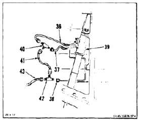
20.
Tag and disconnect three hoses (36, 37, and 38)
from left ramp actuator (39).
21.
Connect two hoses (36 and 37) to tee (40).
22.
Connect hose (41) to tee (40) and tee (42).
23.
Connect hose (38) to tee (42).
24.
Connect test stand return hose (43) to tee (42).
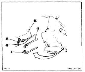
25.
Working at aft right landing gear, tag and
disconnect DOOR EXTEND hose (44) from filling
(45) on ramp (46).
26.
Tag and disconnect DOOR RETRACT hose (47)
from filling (48) on ramp (46).
27.
Connect hose (47) to hose (44).
Do not exceed 500 psi. Otherwise
damage to components can occur.
Keep test stand bypass valve closed.
Otherwise, contaminants could
re-enter the system.
28.
Apply hydraulic power. Set stand to 10 gpm at
500 psi. Flush system for 15 minutes. Check
for leaks.
29.
Remove hydraulic power.
30.
Disconnect hose (44) from hose (47).
31.
Connect DOOR EXTEND hose (44) to filling (45)
on ramp (46). Remove tag.
32.
Connect DOOR RETRACT hose (47) from fitting
(48) on ramp (46). Remove tag.
INSPECT
7-1191