TM 55-1520-240-23-5
6-24
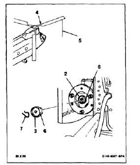
INSTALL COMBINING TRANSMISSION AFT OUTPUT SHAFT ADAPTER
ASSEMBLY
(Continued)
6-24
4.
Coat thread of retainer (3) with grease (E190.1).
5.
Have helper hold rotor blade (4) in position with
tiedown line (5).
6.
Install retainer (3) in adapter assembly (2).
Torque retainer to 825 inch-pounds continue
torquing to align holes (6) in retainer (3) and
adapter assembly (2).
7.
Install locking (7). Check that lockring protrudes
through adapter assembly (2) at least 0.060 inch.
INSPECT
FOLLOW-ON MAINTENANCE:
Install aft drive shafting (Task 6-29).
Remove tiedown line from rotor blade (Task 1-26).
Perform ground run (TM 55-1520-240-10).
END OF TASK
6-70