TM 55-1520-240-23-5
6-217
VIBRATION CORRECTION PROCEDURE (AVIATION VIBRATION
ANALYZER) (Continued)
6-217
ENGINE DRIVE SHAFTS
NOTE
Adjust No. 1 and No. 2 engine drive
shaft in the same way. No. 2 engine
drive shaft shown.
1.
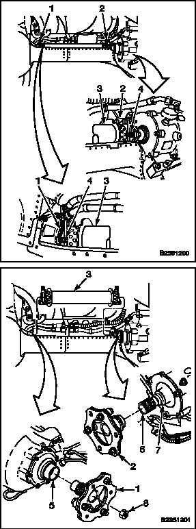
Inspect adapter assemblies (1 and 2) at each
end of shaft (3) (Task 6-30.1).
2.
Loosen nuts (4) at adapter assemblies (1 and 2)
of shaft (3). Hold bolt heads to keep bolts from
turning.
CAUTION
If bolts are allowed to turn, bolts,
plates and shaft adapter assembly
can be damaged.
3.
Torque nuts (4) to 440 inch-pounds.
4.
Perform a vibration check for engine drive
shafts. If vibration is not greater than 1.0 ips,
go to Follow-On Maintenance. If check is
unsatisfactory (vibration greater than 1.0 ips),
continue with step 5.
5.
Match-mark each drive shaft (3) to adapters
(1 and 2). Match-mark adapter (1) to engine
transmission (5) and adapter (2) to combining
transmission (6). Use a marking pencil (E270.1).
6.
Remove drive shaft (3) and adapters (1 and 2)
(Task 6-30). Inspect shaft and adapters (Task
6-30.2). Check interior of shaft for water and
foreign objects.
WARNING
Dry cleaning solvent (E162) is
combustible and toxic. It can irritate
skin and cause burns. Use only with
adequate ventilation, away from open
flame. In case of contact, immediately
flush skin or eyes with water for
at least 15 minutes. Get medical
attention for eyes.
7.
Clean splines on adapters (1 and 2), splines (7)
on combining transmission (6), thread of nut (8),
and mating stud within engine transmission (5).
Use solvent (E162) and cloths (E120). Wear
gloves (E184.1).
8.
Inspect all splines for wear or damage.
9.
Install adapters (1 and 2) and drive shaft (3)
(Task 6-32). Make sure all match-marks line up.
Change 1
6-709


