TM 55-1520-240-23-5
6-16
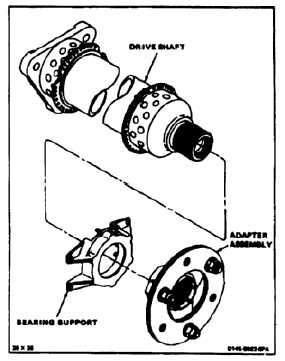
ASSEMBLE DRIVE SHAFT
6-16
INITIAL SETUP
Applicable Configurations:
All
Tools:
Powertrain Tool Kit, NSN 5280-00-323-5267
Torque Wrench, 30 to 150 Inch-Pounds
Torque Wrench, 700 to 1600 Inch-Pounds
Aluminum Tube, 3 Inch ID, 1/8 Inch Thick Wall, 1 to
6 Inches Long
Arbor Press
Materials:
Grease (E190)
Antiseize Compound (E75)
Cloths (E120)
Parts:
Cotter Pin
Personnel Required:
Aircraft Powertrain Repairer
Inspector
References:
TM 55-1520-240-23P
NOTE
Assembly procedure is for No. 1 thru
No. 6 and No. 8 drive shafts. Typical
shaft shown here.
1.
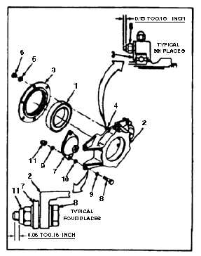
Pack bearing (1) with grease (E190).
2.
Install bearing (1) in bearing support (2). Use
aluminum tube as a tool. Make sure bearing
seats firmly in support.
3.
Install bearing retainer (3) on six studs (4) of
bearing support (2). Smooth side of retainer
shall face out.
4.
Install six washers (5) and nuts (6). Torque nuts
to 60 inch-pounds. Check studs (4). There shall
be 0.15 to 0.18 inch of stud extending through
nut.
5.
Position mount (7) on each side of support (2).
Install bolt (8), two washers (9), thin washer (10)
and nut (11) two places on each mount. Torque
nuts to 35 inch-pounds.
6.
Check bolts (8). There shall be 0.06 to 0.16 inch
of bolt extending through each nut (11).
6-48