TM 55-1520-240-23-5
6-16
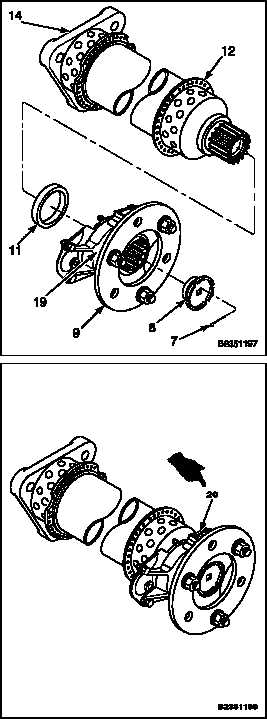
ASSEMBLE DRIVE SHAFT (Continued)
6-16
10.
Install spacer (11) on adapter assembly (9).
NOTE
If adapter assembly and shaft
assembly does not have the same
serial number, they must be returned
to depot facility for balancing.
11.
Check that adapter assembly (9) and drive shaft
assembly (12) have the same vibro-engraved
or stenciled serial number. If stenciled serial
number is not readable, check that the
vibro-engraved serial number in the adapter
assembly and drive shaft assembly match with
serial number recorded in DA FORM 2410 or
2408-16.
12.
Apply a light coat of grease (E190) to splines of
adapter assembly (9) and drive shaft assembly
(12). Wipe off excess grease with cloth (E120).
Wear gloves (E184.1).
13.
Align leg (19) marked as number 1 on adapter
assembly (9) with leg marked as number 2 on
the drive shaft (12) adapter flange (14). Install
adapter assembly (9) on the splines of drive shaft
assembly (12).
NOTE
If new retainer assembly is not
available, a used retainer assembly
may be used, provided the two nylon
inserts are present.
14.
Check retainer assembly (8) for presence of
two nylon self-locking inserts. Coat threads
of retainer assembly threads with antiseize
compound (E75). Wear gloves (E184.1). Install
retainer assembly in drive shaft assembly
(12). Check for a run on torque of at least 60
inch-pounds for a used retainer assembly or
180 inch-pounds for a new retainer assembly.
15.
Torque retainer assembly (8) to 1500
inch-pounds. Continue to tighten retainer
assembly until slot in retainer aligns with holes in
the adapter assembly (9). Install cotter pin (7),
with head on the inside of the retainer assembly
(8).
16.
Add grease (E190) at fitting (20).
INSPECT
FOLLOW-ON MAINTENANCE:
None
END OF TASK
6-50
Change 1