TM 55-1520-240-23-5
6-76
ASSEMBLE COMBINING TRANSMISSION (Continued)
6-76
1.
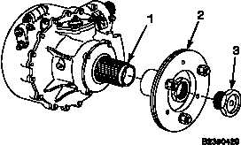
Clean splines on aft output shaft (1) and adapter
assembly (2). Use dry cleaning solvent (E162)
and clean cloth (E120). Wear gloves (E186) and
goggles (E473).
2.
Pack splines on output shaft (1) and adapter
assembly (2) with grease (E190.1).
3.
Install adapter assembly (2) on output shaft (1).
Wipe off excess grease with cloths (E120).
4.
Coat thread of retainer (3) with grease (E190.1).
Install retainer.
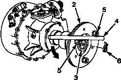
5.
Place wood dowel (4) across nuts (5) as shown.
Hold dowel to keep adapter assembly (2) from
turning. Torque retainer (3) to 825 inch-pounds.
Continue tightening to align holes in retainer and
adapter assembly.
6.
Install lockring (6). Check that lockring protrudes
through adapter assembly (2) at least 0.060 inch.
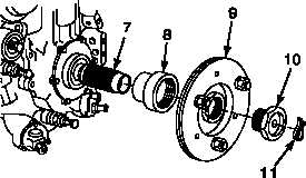
7.
Clean splines on forward output shaft (7),
retainer (8), and adapter assembly (9). Use
solvent (E162) and clean cloth (E120). Wear
gloves (E186) and goggles (E473).
8.
Pack splines on shaft (7), retainer (8), and
adapter assembly (9) with grease (E190.1).
9.
Install retainer (8) and adapter assembly (9)
on shaft (7). Wipe off excess grease with cloth
(E120).
10.
Loosely install retainer (10) to align holes in
retainer and adapter assembly (9). Install
lockring (11).
NOTE
Adapter assembly is adjusted and
torqued during sync shaft installation.
Change 1
6-291