TM 55-1520-240-23-5
6-29
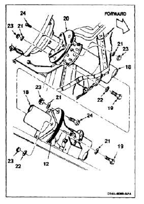
INSTALL AFT DRIVE SHAFTING
(Continued)
6-29
INSTALL NO. 9 SHAFT
NOTE
If position of adapter assemblies is
changed, rotor blades will have to be
phased again.
9.
Have helper support No. 9 shaft (18). Remove
two bolts (19) inserted during phasing. Do not
disturb positions of adapter assemblies (12 and
20).
10.
Coat thread of six bolts (19) with oil (E254).
Install three bolts, heads forward, and special
washers (21) through adapter assembly (12) and
shaft (18). Install three bolts, heads forward,
and washers (22) through shaft (18) and adapter
assembly (20).
11.
Loosely install three washers (22) and nuts
(23) on forward bolts (19). Loosely install three
special washers (21) and nuts (23) on aft bolts.
12.
Coat thread of two bolts (24) with oil (E254).
Install bolts, heads away from each other,
through adapter assemblies (12 and 20). Install
special washer (21) and nut (23) on each bolt.
Do not let bolts turn. If bolts turn,
damage to bolts and plates can result.
13.
Have helper hold head of six bolts (19) and two
bolts (24) with wrench. Torque eight nuts (23) to
1000 to 1100 inch-pounds.
INSPECT
FOLLOW-ON MAINTENANCE:
Install aft transmission drip tray (Task 2-3).
Close baffles under aft transmission (Task 2-2).
Close aft drive shaft access panel (Task 2-2).
Close aft pylon lower fairing (Task 2-2).
Close aft pylon doors (Task 2-2).
Close cargo ramp (Task 2-2).
Perform a combining transmission oil cooler fan
vibration check (TM 1-6625-724-13&P).
Perform ground run (TM 55-1520-240-10).
END OF TASK
6-83