TM 55-1520-240-23-5
6-28
PHASE ROTARY-WING BLADES
(Continued)
6-28
4.
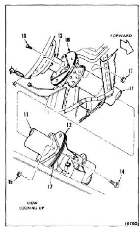
Temporarily install No. 9 drive shaft as follows:
a.
Have helper support shaft (11) between
No. 8 shaft adapter assembly (12) and aft
transmission adapter (13).
b.
Loosely install two bolts (14) and nuts (15)
through adapter assembly (12) and forward
end of shaft (11).
NOTE
If No. 9 shaft and aft transmission
adapter do not line up, the adapter
must be removed and rotated until
alignment is obtained.
c.
Loosely install two bolts (16) and nuts (17)
through adapter (13) and No. 9 shaft adapter
(18).
5.
Remove two phasing blocks of step 2.
6.
Rotate blades three complete revolutions in the
leading direction. Check phasing by installing
two phasing blocks as in steps 2 and 3. Remove
blocks.
7.
Permanently install No. 9 drive shaft (Task 6-29).
INSPECT
FOLLOW-ON MAINTENANCE:
Close forward transmission fairing left work platform
(Task 2-2).
Close aft pylon work platform (Task 2-2).
Remove tiedown lines from rotary-wing blades (Task
1-26).
END OF TASK
6-79


