TM 55-1520-240-23-3
4-109
INSTALL GAS PRODUCER CONTROL ACTUATOR
4-109
INITIAL SETUP
Applicable Configurations:
Without 74
Tools:
Powerplant Repairer’s Tool Kit, NSN
5180-00-323-4944
Torque Wrench, 5 to 50 Inch-Pounds
Materials:
Lockwire (E231)
Personnel Required:
Aircraft Powerplant Repairer
Inspector
References:
TM 55-1520-240-23P
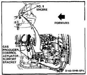
NOTE
Procedure is same to install gas
producer control actuator on No. 1 or
No. 2 engine. No. 1 engine is shown
here.
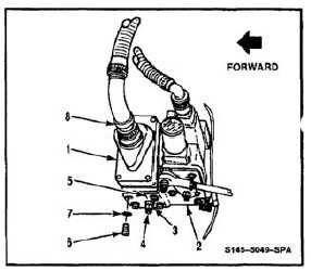
1.
Position actuator (1) on bracket (2). Check index
mark (3) on actuator shaft (4). Index mark shall
align with index mark (5) on bracket.
Screws must be lockwired left to right.
Interference or damage to control rod
could result if screws are lockwired
up and down.
2.
Install four screws (6) and washers (7). Lockwire
screws left to right. Use lockwire (E231).
3.
Connect cable connector (8).
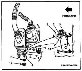
4.
Position lever (9) on shaft (4). Index mark (10) on
lever shall align with index mark (5) on bracket
(2). Install washer (11) and nut (12) on shaft.
Torque nut to 35 inch-pounds.
INSPECT
FOLLOW-ON MAINTENANCE:
Perform operational check of gas producer control
system (TM 55-1520-240-T).
Close engine access cover (Task 4-50).
Close engine work platform (Task 2-2).
END OF TASK
4-394