TM 55-1520-240-23-3
4-13
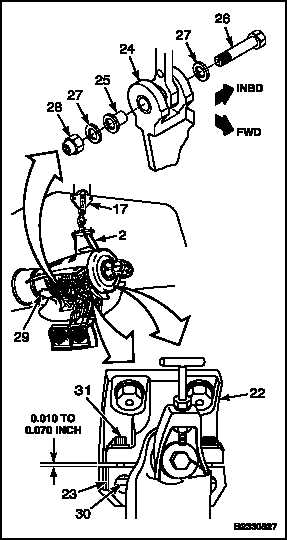
INSTALL POWERPLANT (Continued)
4-13
CAUTION
Make sure powerplant weight is on aft
support link and not on firewall former.
Damage to powerplant and former
can occur if weight is not on support
link.
9.
Install slip fit bushing (25), shoulder outboard,
in clevis (24).
10.
Install bolt (26), two washers (27), and nut (28).
Raise or lower powerplant (2) as needed for
clearance.
11.
Adjust firewall former (29) (Task 4-44).
12.
Relax tension on hoist (17).
13.
Torque nut (28) to 350-400 inch-pounds to
seat bushing. Loosen nut and retorque to 20
inch-pounds above run-on torque. Not to be
less than 70 inch-pounds.
INSPECT
14.
Check barrel nuts (30). Breakaway torque shall
not be less than 7 inch-pounds.
15.
Push four bolts (31) up and over adapter (22)
and tighten evenly.
16.
Torque bolts (31) to 20 inch-pounds above
friction torque.
NOTE
It is acceptable for clearances to vary
inboard to outboard and/or forward
to aft providing the clearance at any
point is within the defined limits.
17.
Measure gap between adapters (22) and caps
(23). Gap shall measure 0.010 to 0.070 inch.
18.
Torque bolts (31) to 105 inch-pounds.
19.
Measure gap between adapters (22) and caps
(23). Gap shall measure 0.010 to 0.070 inch.
NOTE
It is acceptable for clearances to vary
inboard to outboard and/or forward
to aft providing the clearance at any
point is within the defined limits.
20.
Check bolts (31). Bolts shall protrude a minimum
of two threads through barrel nuts (30), but shall
not bottom out. Add washers under bolthead
if bolt is bottoming out. Lockwire bolts. Use
lockwire (E231).
Change 1
4-111