TM 55-1520-240-23-10
16-59.9
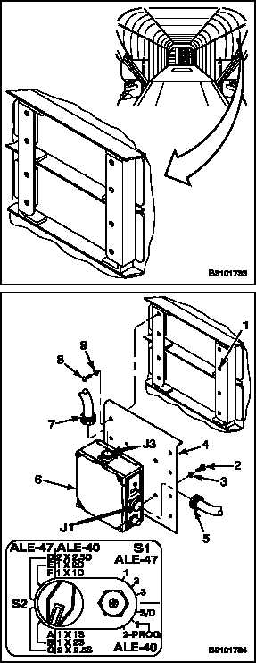
INSTALL AN/ALE-47 SEQUENCER
16-59.9
INITIAL SETUP
Applicable Configurations:
All
Tools:
Electronic Equipment Tool Kit,
NSN 5180-00-064-5178
Materials:
Lockwire (E229)
Personnel Required:
Avionics Mechanic
Inspector
Equipment Condition:
Battery Disconnected (Task 1-39)
Electrical Power Off
Hydraulic Power Off
AN/ALE-47 Safety Switch Pin Installed
(TM 1-1520-240-10)
NOTE
Procedures to install the LH and RH
sequencers are the same.
1.
Position sequencer (6) on mounting plate (4) and
secure with four screws (2) and washers (3).
2.
Position sequencer mounting plate (4) and
sequencer (6) to the mounting bracket (1) and
secure with eight screws (8) and washers (9).
3.
Perform bonding check of electrical components
per Task 16-59.28.
4.
Remove caps and connect two electrical
connectors (5 and 7) to J1 and J3 receptacles on
sequencer (6). Remove tag.
NOTE
Ensure sequencer switches are set
as follows:
LH (No. 1) Sequencer — 1A
RH (No. 2) Sequencer — 2A
Graphic depicts setup for No. 2
sequencer.
5.
Safety wire sequencer switches using lockwire
(E229).
INSPECT
FOLLOW-ON MAINTENANCE:
Perform operational check of countermeasures
dispenser system (TM 55-1520-240-T).
Close cargo ramp (TM 55-1520-240-T).
END OF TASK
Change 1
16-250.19