TM 55-1520-240-23-10
14-1
CARGO HANDLING SYSTEM
(Continued)
14-1
7.
A shifting lever on the winch controls a two-speed
gear train, labeled RESCUE (fast) and CARGO
(slow). With the lever at RESCUE, the cable
cutter must be plugged into the overhead CABLE
CUTTER connector to complete the winch circuit.
With the lever at CARGO, the cable cutter must
be plugged into the stowage receptacle at sta
95 to complete the circuit. The shifting lever is
mechanically linked to three transfer switches.
These switches connect voltage to either the
rescue or cargo in-limit switch. When the lever
is at RESCUE, the rescue (fast) in-limit switch
is connected in series with switch 1. With the
lever at CARGO, the cargo (slow) in-limit switch
is connected in series with switch 2. Switch 3
is a safety device which interrupts the hoist-out
circuit when switches 1 and 2 are open. This
arrangement prevents the winch from operating
in either direction when the gears are not
engaged.
8.
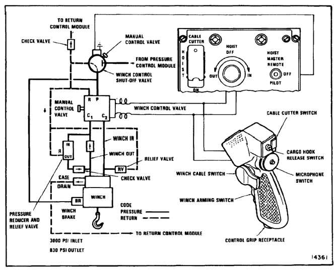
In case of electrical failure, emergency hydraulic
operation of the winch is possible by operating
manual override knobs on the winch control
shutoff valve and the winch control valve. The
knob on the shutoff valve is an on-off valve that
allows fluid to flow through the system when
it is pushed in. It can be locked in by rotating
it. Winch reeling direction (cable in or out) is
controlled by rotating the knob on the control
valve cw or ccw. When the manual override
knobs are used, the cable limit switches are
disabled. As a result, care is necessary to
prevent reeling the cable too far in or out.
14-5


