TM 55-1520-240-23-9
11-241
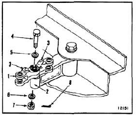
INSTALL TUNNEL CONTROL ARMS
(Continued)
11-241
INSTALL CONTROL ARMS AT STA 163 AND 401
FLIGHT SAFETY PARTS
This is an installation critical flight
safety part. All aspects of its assembly
and installation must be ensured at
each joint connection and mounting to
the airframe.
Ensure that bearings are properly
installed and located (2 places) in
each clevis of the walking beam.
Ensure walking beam hub bearings
are serviceable, secure and properly
installed.
Ensure the locating pads on the
walking beam forging are installed
facing up at all locations.
Ensure proper attaching hardware
(impedance type bolt, nut, and
washers) is installed including
verification of bolt head orientation,
torque, and installation of cotter pins.
Loose attachments within flight control
primary linkage will degrade aircraft
control. Missing components will
cause loss of control.
Bellcrank must be positioned with side
marked TOP facing up; otherwise,
serious damage to components can
occur.
1.
Remove tag and position control arm (1) on idler
(2) with pads (3) and the word TOP up.
2.
Install bolt (4), two washers (5 and 6), and nut
(7). Torque nut to 85 to 125 inch-pounds. Install
cotter pin (8).
3.
Check bolt (4). Bolt shall not rotate with torque
less than 10 inch-pounds. Bolt shall have no
axial looseness. If bolt rotates or is loose, add
washer under nut and repeat step 2.
11-936