TM 55-1520-240-23-9
11-240
REMOVE TUNNEL CONTROL ARMS
11-240
INITIAL SETUP
Applicable Configurations:
All
Tools:
Aircraft Mechanic’s Tool Kit, NSN 5180-00-323-4692
Materials:
Paper Tags (E264)
Personnel Required:
Medium Helicopter Repairer
References:
TM 1-1520-253-23
Equipment Condition:
Battery Disconnected (Task 1-39)
Electrical Power Off
Hydraulic Power Off
Tunnel Access Doors No. 3 and No. 6 Open (Task
2-2)
Safety Blocks (T31) Installed (Task 11-28)
Servocylinder Connecting Links Disconnected (Task
11-192)
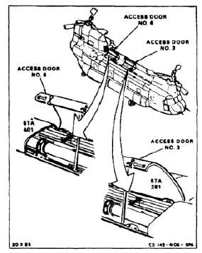
NOTE
Procedure is same for all tunnel
control arms. Control arms are
located at sta. 163, 201, 241, 281,
321, 361, and 401. Control arms sta.
281 and 401 are shown here.
NOTE
If a crack in the connecting links is
suspected during removal, refer to TM
1-1520-253-23.
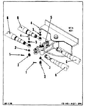
REMOVE CONTROL ARM AT STA 401
1.
Remove two cotter pins (1), two nuts (2), four
washers (3), and two bolts (4) from control arm
(5).
2.
Disconnect four connecting links (6) from control
arm (5).
11-933