TM 55-1520-240-23-9
11-176
ADJUST ROLL OR YAW CONTROL POSITION TRANSDUCER (CPT)
(Continued)
11-176
ADJUST YAW CPT
19.
Repeat steps 1 and 2.
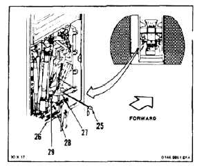
20.
Install thrust and yaw idler bellcrank rig pin
(T134) (25) through support (26), two bellcranks
(27 and 28), and in support (29).
21.
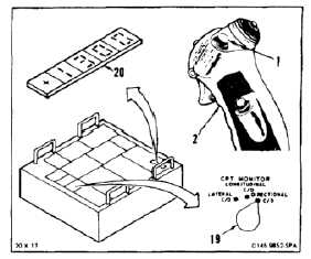
Have helper release switch (1) of stick (2).
22.
Repeat steps 5 and 6.
23.
Set CPT MONITOR switch (19) to
DIRECTIONAL.
24.
Check digital display (20). Display must indicate
between -0.050 to +0.050 vac. If indication is
within limits, go to step 30. If not, perform steps
25 thru 28, then go to step 30.
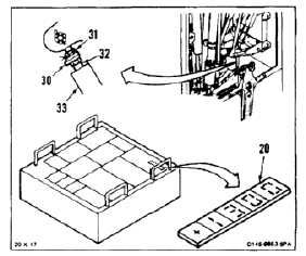
25.
Remove lockwire from lockwasher (30) and nut
(31) of yaw position transducer (32). Loosen nut.
26.
Turn outer shell (33) of transducer (32) until
display (20) indicates between -0.050 to +0.050
vac.
27.
Align lockwasher (30) and tighten nut (31).
Lockwire nut to lockwasher. Use lockwire (E231).
11-701