TM 55-1520-240-23-9
11-177
ADJUST PITCH CONTROL POSITION TRANSDUCER (CPT)
(Continued)
11-177
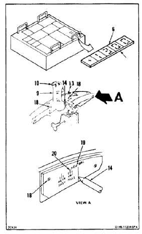
9.
Have helper press switch (10) and move stick (9)
until indication on display (6) is same as recorded
in step 4. Release switch.
10.
Loosen two screws (18) on plate (13). Align
NEUTRAL line (19) on plate with pointer (14).
Tighten screws. Check display (6) is same as
recorded in step 4.
11.
Press switch (10) and move stick (9) aft until
pointer (14) is at CPT NULL line (20). Release
switch.
12.
Check display (6). Display must indicate between
-0.05 +0.05 vac. If indication is within limits, go
to step 16. If not, perform steps 13 thru 15, then
go to step 16.
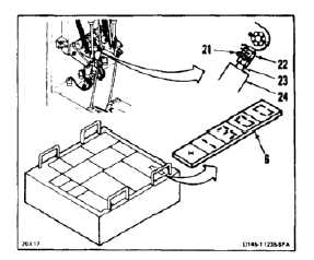
13.
Working in passageway remove lockwire from
lockwasher (21) and nut (22) of pitch position
transducer (23). Loosen nut.
14.
Turn outer shell (24) of transducer (23) until
display (6) indicates between -0.05 +0.05 vac.
15.
Align lockwasher (21) and tighten nut (22).
Lockwire nut to lockwasher. Use lockwire (E231).
11-705