TM 55-1520-240-23-9
11-84
INSTALL STICK PITCH POSITION INDICATOR
(Continued)
11-84
Do not kink or deform tubing or cable;
otherwise, damage to component will
result.
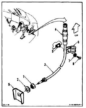
1.
Slide nut (1) and washer (2) on tube (3). Position
tube and adjuster (4) in structure (5) with adjuster
up.
2.
Position clamp (6) on tube (3) just below adjuster
(4). Install washer (7) and screw (8) in clamp
and mount (9).
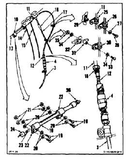
3.
Position indicator (10), tube (11), and cable (12)
on right of console (13). Guide cable and tube
inboard of three controls (14, 15, and 16) then
outboard of rod (17).
4.
Insert cable (12) into adjuster (4) and tube (3)
until nut (18) touches adjuster.
5.
Install nut (18) in adjuster (4).
6.
Install four bolts (19), eight washers (20), and
four nuts (21) in two mounts (22) of indicator (10).
7.
Install lamp (23) indicator (10).
8.
Connect cap (24) to indicator (10).
9.
Position clamp (25) on tube (11) and under
clamp (26). Install washer (27) and screw (28) in
clamps and mount (29).
10.
Position clamp (30) on tube (11). Position spacer
(31) between clamp (30) and clamp (32). Install
bolt (33), two washers (34), and nut (35).
11.
Tighten nut (36). Lockwire nut to indicator (10).
Use lockwire (E231).
11-443