TM 55-1520-240-23-9
11-78
ASSEMBLE COPILOT’S COCKPIT CONTROL ASSEMBLY
(Continued)
11-78
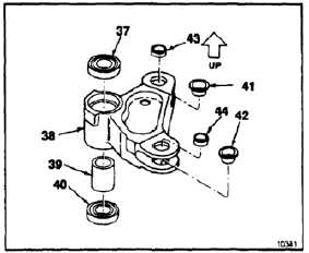
ASSEMBLE THRUST IDLER BELLCRANK
17.
Press bearing (dissimilar metals) (37) in thrust
idler bellcrank (38) until it bottoms. (Refer to TM
55-1520-322-24.) Use arbor press.
18.
Install spacer (39) in bellcrank (38).
19.
Press bearing (dissimilar metals) (40) in
bellcrank (38) until it bottoms. (Refer to TM
55-1500-322-24.) Use arbor press.
20.
Install two bushings (dissimilar metals) (41 and
42) flange inward, in lower lugs of bellcrank (38).
21.
Install two bushings (dissimilar metals) (43 and
44) in upper lugs of bellcrank (38).
INSPECT
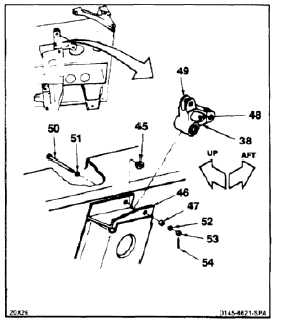
INSTALL THRUST IDLER BELLCRANK
22.
Install bushing (dissimilar metals) (45) flange
inward, in upper arm of support (46).
23.
Install bushing (dissimilar metals) (47) lower arm
of support (46).
FLIGHT SAFETY PARTS
This is an installation critical flight
safety part. All aspects of its assembly
and installation must be ensured at
each joint connection and mounting to
the airframe.
Ensure that all bushings are properly
installed (including orientation) in
the output and input clevises of the
bellcrank assembly.
Ensure bellcrank hub bearings are
serviceable and properly installed.
Ensure associated bushings are
properly installed in the adjacent
support assembly.
Ensure proper attaching hardware
(impedance type bolt, nut, and
washers) is installed including
verification of bolt head orientation,
torque, and installation of cotter pins.
Loose attachments within flight control
primary linkage will degrade aircraft
control. Missing components will
cause loss of control.
Bellcrank shall be positioned as
indicated by marks on bellcrank;
otherwise, serious damage to
components can occur.
24.
Position bellcrank (38) in support (46) hole (48)
aft and arm (49) up.
25.
Install bolt (50), two washers (51 and 52), and
nut (53) in support (46). Remove tag from
bellcrank (38).
26.
Torque nut (53) to 30 inch-pounds. Continue
tightening to align cotter pin holes. Do not
exceed 45 inch-pounds. Install cotter pin (54).
27.
Check bolt (50). Bolt shall not rotate with torque
less than 10 inch-pounds. There shall be no
axial looseness. If bolt rotates or is loose, add
washer under nut and repeat step 26.
11-386