TM 55-1520-240-23-9
11-67
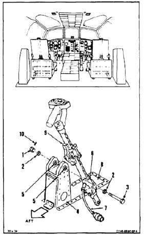
INSTALL THRUST CONTROL (COPILOT)
(Continued)
11-67
NOTE
Impedance bolts are installed in flight
control connections. These bolts are
self-retaining and require a special
nut and torque (Task 1-13).
1.
Remove nut (1), washers (2), and bolt (3) from
support (4). Make sure bushings (5) are in place
in support.
FLIGHT SAFETY PARTS
This is an installation critical flight
safety part. All aspects of its assembly
and installation must be ensured at
each joint connection and mounting to
the airframe.
Ensure smooth operation of ball slide
assembly.
Ensure thrust grip assembly is
secured to the lever assembly,
including the grip wire bundle,
associated clamping arrangement,
and connector.
Ensure that all bushings are properly
installed (including orientation) in the
adjacent structural support.
After verification of proper installation
of the pivot hardware, apply sealant
over cotter pin sharp edges to prevent
tearing of the boot assembly.
Orient lower end of thrust lever
attaching hardware so as to provide
maximum amount of clearance with
the cockpit floor opening.
Ensure routing of grip wire bundle
under the floor does not interfere with
the full thrust lever motion as defined
in the flight controls motions check.
Ensure proper attaching hardware
(impedance type bolt, nut, and
washers) is installed including
verification of bolt head orientation,
torque, and installation of cotter pins.
Loose attachments within flight control
primary linkage will degrade aircraft
control. Missing components will
cause loss of control.
2.
Position lower end of thrust control (6) and cable
(7) through opening (8) in cockpit floor. Pivot
block (9) shall face aft.
3.
Position pivot block (9) in support, install bolt
(3), head inboard, two washers (2), and nut (1).
Torque nut to 30 to 45 inch-pounds.
4.
Check bolt (3). Bolt shall not rotate with a torque
less than 10 inch-pounds. Bolt shall not have
axial looseness. If bolt rotates or is loose, add
washer under nut. Torque and cotter pin nut
again.
4.1.
Apply sealant (E340) over nut (1) and cotter pin
(10). Cover all sharp edges.
INSPECT
11-305