TM 55-1520-240-23-9
11-277
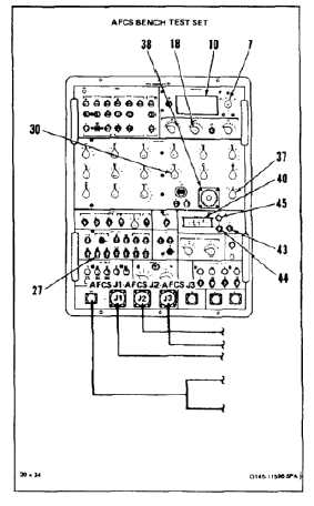
BENCH TEST AFCS COMPUTER (AVIM)
(Continued)
11-277
181.
Set RESPONSE TEST STIM switch (44) to
REMOVE.
182.
Set ANALOG SIGNALS ATT synchro (38) to 0.0º.
183.
Set ANALOG SIGNALS ATT SELECT switch
(37) to HDG.
184.
Set RESPONSE TEST MODE switch (43) to
OFF.
185.
Set DISCRETE SIGNALS CYCLIC BRAKE
switch (27) to 1 momentarily and then to 0.
186.
Set CIRCUIT SELECT A UNITS switch (18) to 4.
187.
Set METER RANGE switch (7) to 2V. Read and
record V1 reading on AC/DC VOLTMETER (10).
Reading shall be -0.64 to +0.64.
188.
Set RESPONSE TEST MODE switch (43) to ON.
189.
Set ANALOG SIGNALS ROLL RATE switch (30)
to 4.
190.
Set RESPONSE TEST TIME DELAY-SEC
switches (40) to 0.021.
191.
Set METER RANGE switch (7) to 20V.
192.
Set RESPONSE TEST STIM switch (44) to
APPLY. When HOLD lamp (45) comes on, read
and record V2 AC/DC VOLTMETER (10) reading.
193.
Calculate V3. Subtract reading of step 187 from
reading of step 192 (V3 = V2 - V1). Result shall
be -3.15 to -4.73 volts.
11-1089