TM 55-1520-240-23-1
1-59
POWER SERVICE UTILITY HYDRAULIC SYSTEM RESERVOIR (Continued)
1-59
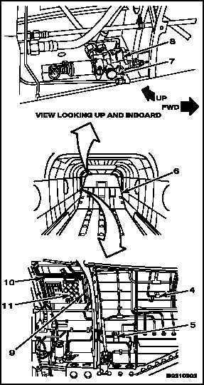
3.
Make sure UTILITY RESERVOIR
DEPRESSURIZE valve (4) and EMERG
UTIL PRESS valve (5) are set to NORMAL.
4.
Press and hold depressurization valve (7) on
APU start module (8) until accumulators have
discharged completely.
5.
Release valve (7).
6.
Turn valve (4) to OPEN.
NOTE
Be sure to read correct scale on
gauge according to whether ramp is
fully up or fully down.
7.
Press and hold LEVEL CHECK button (9) on
MAINTENANCE PANEL (10). Read reservoir
fluid level on gauge (11).
8.
Have helper operate test stand. Set test stand
flow limits to minimum flow position. Turn on
test stand. Set stand pressure between 500
and 1000 psi (TM 55-4920-335-14 or TM
55-4920-373-14&P).
9.
Have helper press and hold valve (7). Press
button (9) and read gauge (11).
10.
When gauge (11) indicates FULL, release valve
(7), and button (9). Turn valve (4) to NORMAL.
11.
Shut down test stand.
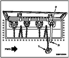
12.
Disconnect test stand pressure line (3) from
utility pressure connection (2).
13.
Replace dust cover (1) on utility pressure
connection.
1-228