TM 55-1520-240-23-1
1-59.1
POWER DRAIN UTILITY HYDRAULIC SYSTEM RESERVOIR (Continued)
1-59.1
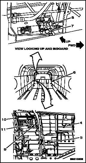
3.
Make sure UTILITY RESERVOIR
DEPRESSURIZE valve (4) and EMERG
UTIL PRESS valve (5) are set to NORMAL.
4.
Press and hold depressurization valve (7) on
APU start module (8) until accumulators deplete
to precharge.
5.
Release valve (7).
6.
Turn valve (4) to OPEN.
NOTE
Be sure to read correct scale on
gauge according to whether ramp is
fully up or fully down.
7.
Press and hold LEVEL CHECK button (9) on
MAINTENANCE PANEL (10). Read reservoir
fluid level on gauge (11).
8.
Have helper operate test stand. Turn on
test stand (TM 55-4920-335-14 or TM
55-4920-373-14&P).
9.
Have helper press and hold valve (7). Press
button (9) and read gauge (11).
10.
When gauge (11) indicates EMPTY, release valve
(7), and button (9). Turn valve (4) to NORMAL.
11.
Shut down test stand.
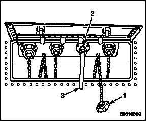
12.
Disconnect test stand return line (3) from utility
RETURN connection (2).
13.
Replace dust cover (1) on utility RETURN
connection.
FOLLOW-ON MAINTENANCE:
Disconnect battery (Task 1-39).
Close hydraulic connection access panel (Task 2-2).
END OF TASK
1-231