TM 55-1520-240-23-9
11-243
INSTALL TUNNEL CONTROLS IDLER
(Continued)
11-243
FLIGHT SAFETY PARTS
This is an installation critical flight
safety part. All aspects of its assembly
and installation must be ensured at
each joint connection and mounting to
the airframe.
Ensure that the flanged bushings are
properly installed.
Ensure idler assembly hub bearings
are serviceable, secure and properly
installed.
Ensure clearance cut is present on
top side off all idler assemblies and
a minimum of 0.06 inch clearance
exists in that area to adjacent
connecting link attaching hardware.
Ensure proper attaching hardware
(impedance type bolt, nut, and
washers) is installed including
verification of bolt head orientation,
torque, and installation of cotter pins.
Loose attachments within flight control
primary linkage will degrade aircraft
control. Missing components will
cause loss of control.
NOTE
Procedure is same for all tunnel
control idlers. Idlers are located at sta.
163, 201, 241, 281, 321, 361, and
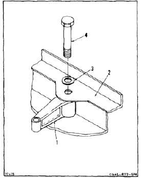
401. Idler at sta. 281 is shown here.
All bolts installed in flight control
system are self-retaining impedance
bolts. During installation of flight
controls make sure all bolts used are
self-retaining bolts.
1.
Position tunnel control idler (1) in structure (2).
2.
Install washer (3) and bolt (4) through idler (1).
3.
Hold bolt (4) with wrench while helper works in
cabin area.
11-944