TM 55-1520-240-23-9
11-191
INSTALL SECOND STAGE MIXING ASSEMBLY
(Continued)
11-191
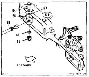
CONNECT LOWER INBOARD LINK
39.
Move bellcrank (28) forward for access to bolt
(64). Remove nut (65), and two washers (66 and
67) and bolt (64).
40.
Position lower inboard link (68) in bellcrank (28).
Install bolt (64), two washers (67 and 66) and nut
(65). Do not torque nut at this time. Remove tag.
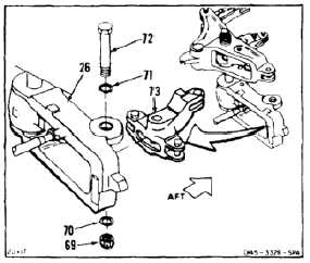
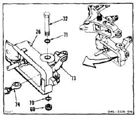
INSTALL AFT OUTPUT BELLCRANK AND CONNECT
LOWER OUTBOARD LINK
41.
Remove nut (69), two washers (70 and 71), and
bolt (72) from bellcrank (26).
FLIGHT SAFETY PARTS
This is an installation critical flight
safety part. All aspects of its assembly
and installation must be ensured at
each joint connection and mounting to
adjacent bellcrank assembly.
Ensure that all bushings are properly
installed (including orientation) in
each input and output clevis of the
bellcrank.
Ensure bellcrank hub bearings are
serviceable and properly installed.
Ensure proper attaching hardware
(impedance type bolt, nut, and
washers) is installed including
verification of bolt head orientation,
torque, and installation of cotter pins.
Loose attachments within flight control
primary linkage will degrade aircraft
control. Missing components will
cause loss of control.
42.
Position aft output bellcrank (73) in bellcrank
(26), long arm aft.
43.
Position lower outboard link (74) in center clevis
of bellcrank (73).
44.
Install bolt (72) through washer (71) bellcranks
(26 and 73), and link (74).
45.
Install washer (70) and nut (69) on bolt (72). Do
not torque nut at this time.
46.
Check bellcrank (73). Bellcrank shall be free to
move through full range of travel. Remove tags.
11-780


