TM 55-1520-240-23-9
11-183
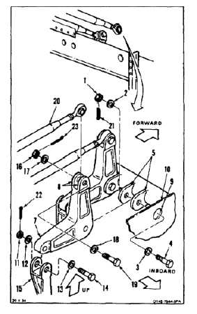
INSTALL YAW OR THRUST INTERMEDIATE BELLCRANKS
(Continued)
11-183
Make sure bushings are in bellcrank,
link, and support lugs, before installing
bolts or component damage will result.
NOTE
Procedure is same to install yaw or
thrust intermediate bellcranks. Thrust
bellcrank is shown here.
Impedance bolts are installed in flight
control connections. These bolts are
self-retaining and require a special
nut and torque (Task 1-13).
1.
Remove nut (1), two washers (2 and 3), and bolt
(4) from lugs (5) of support (6).
FLIGHT SAFETY PARTS
This is an installation critical flight
safety part. All aspects of its assembly
and installation must be ensured at
each joint connection and mounting to
the airframe.
Ensure that all bushings are properly
installed (including orientation) in
each input and output clevis of the
bellcrank.
Ensure bellcrank hub bearings are
serviceable and properly installed.
Ensure proper attaching hardware
(impedance type bolt, nut, and
washers) is installed including
verification of bolt head orientation,
torque, and installation of cotter pins.
Loose attachments within flight control
primary linkage will degrade aircraft
control. Missing components will
cause loss of control.
2.
Position thrust intermediate bellcrank (7), lugs (8)
up, between lugs (5). Insert bolt (4) and washer
(3), through hole (9) in structure (10), and install
in lugs (5) and bellcrank.
NOTE
Bolt of yaw bellcrank is installed with
head outboard.
3.
Install washer (2) and nut (1) on bolt (4). Do not
tighten at this time.
4.
Remove nut (11), two washers (12 and 13), and
bolt (14) from link (15).
5.
Position bellcrank (7) in link (15). Install bolt (14),
two washers (13 and 12), and nut (11). Do not
tighten at this time.
6.
Remove nut (16), two washers (17 and 18), and
bolt (19) from link (20).
7.
Untie link (20) and position in bellcrank (7). Install
bolt (19), two washers (18 and 17), and nut (16).
8.
Torque three nuts (1, 11, and 16) to 30 to 45
inch-pounds. Install three cotter pins (21, 22,
and 23).
9.
Check three bolts (4, 14, and 19). Bolts shall not
rotate with torque less than 10 inch-pounds.
There shall be no axial looseness, if bolt rotates
or is loose, add washer under nut and repeat
step 8.
INSPECT
11-723