TM 55-1520-240-23-9
11-167
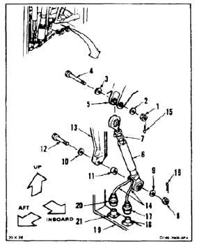
INSTALL YAW POSITION TRANSDUCER
(Continued)
11-167
Bushings must be in bellcrank
and support before installing bolts;
otherwise, damage to components
will result.
NOTE
Impedance bolts are installed in flight
control connections. These bolts are
self-retaining and require a special
nut and torque (Task 1-13).
1.
Remove nut (1), two washers (2 and 3), and bolt
(4) from bellcrank (5).
FLIGHT SAFETY PARTS
This is an installation critical flight
safety part. All aspects of its assembly
and installation must be ensured.
After electrical nulling procedure is
accomplished, ensure adjustable rod
end bearing assembly is properly
saftied by torquing jam nut against
locking tab washer assembly per
BAC5009, and installing safety wire
between jam nut and locking tab
washer assy per BAC5018.
Ensure proper attaching hardware
(impedance type bolt, nut, and
washers) is installed including
verification of bolt head orientation,
torque, and installation of cotter pins.
Loose attachments within flight control
secondary linkage will degrade
aircraft control. Missing components
will cause loss of control.
2.
Position yaw linear transducer (6), adjustable
end (7) up, in bellcrank (5). Install bolt (4), two
washers (3 and 2), and nut (1). Do not tighten
nut at this time.
3.
Remove nut (8), two washers (9 and 10), spacer
(11), and bolt (12) from support (13).
4.
Position transducer (6), wires (14) aft, on support
(13) with spacer (11) between transducer and
support. Install bolt (12), two washers (10 and
9), spacer (11) between support and transducer,
and nut (8).
5.
Torque two nuts (1 and 8) to 30 to 45
inch-pounds. Install two cotter pins (15 and 16).
6.
Check two bolts (4 and 12). Bolts shall not rotate
with torque less than 10 inch-pounds. There
shall be no axial looseness. If bolt rotates or is
loose, add washer under nut and repeat step 5.
Connectors must be installed in fully
locked position; otherwise, component
malfunction can result.
7.
Connect connector (17) of wire with green band
of transducer (6) to inboard receptacle (18) on
structure (19). Remove tag.
8.
Connect connector (20) of wire with red band of
transducer (6) to outboard receptacle (21) on
structure (19). Remove tag.
FOLLOW-ON MAINTENANCE:
Perform yaw linear transducer adjustment check
(Task 11-176).
Perform operational test of advanced flight control
system (TM 55-1520-240-T).
Install closet backup panel (Task 2-2).
Install closet acoustic blanket (Task 2-108).
END OF TASK
11-683