TM 55-1520-240-23-9
11-164
INSTALL DASH ACTUATOR (Continued)
11-164
CAUTION
Bushing must be in bellcranks before
installing bolt; otherwise, damage to
component will result.
NOTE
Impedance bolts are installed in flight
control connections. These bolts are
self-retaining and require a special
nut and torque (Task 1-13).
Prior to installation verify dimension
of upper rod end bearing and check
tightness of rod end checknut.
(Reference Task 11-163.4.)
NOTE
If a crack in the bellcrank is suspected,
refer to TM 1-1520-253-23.
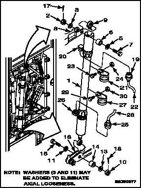
1.
If DASH actuator (1) is a replacement, perform
adjustment check (Task 11-163.2).
2.
Remove nut (2), two washers (3 and 5), bushing
(6), and bolt (7) from upper bellcrank (8).
WARNING
FLIGHT SAFETY PARTS
This is an installation critical flight
safety part. All aspects of its assembly
and installation must be ensured at
each joint connection.
Ensure actuator is installed with
adjustable rod end up.
Ensure actuator is installed at
retracted length of 35.58 to 35.64
inches.
Ensure proper attaching hardware
(self retaining type bolt, nut, and
washers) is installed including
verification of bolt head orientation,
torque, and installation of cotter pins.
Loose attachments within flight control
primary linkage will degrade aircraft
control. Missing components will
cause loss of control.
NOTE
Washers (3) may be added to
eliminate axial looseness.
3.
Position actuator (1), small bearing (9) up and
AFCS connector (20) outboard in bellcrank (8).
Install bolt (7), two washers (5 and 3), bushing
(6), and nut (2). Do not torque nut at this time.
4.
Remove nut (10), two washer (11 and 13),
bushing (14), and bolt (15) from lower bellcrank
(16).
NOTE
Washers (11) may be added to
eliminate axial looseness.
5.
Position actuator (1), AFCS connector (26)
facing outboard in bellcrank (16). Install bolt (15)
bolt head facing outboard, washer (11) under
bolt head, bushing (14) between bellcrank (16)
washer (13) and nut (10).
6.
Torque two nuts (2 and 10) to 30 inch-pounds. If
necessary, continue tightening to align cotter pin
holes. Do not exceed 45 inch-pounds. Install
cotter pins (17 and 18).
Change 1
11-673


