TM 55-1520-240-23-9
11-79
RIG COPILOT’S COCKPIT CONTROL ASSEMBLY
(Continued)
11-79
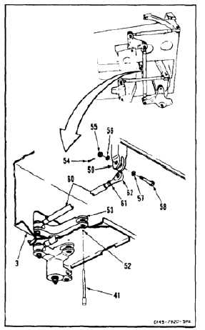
RIG ROLL CONTROL
40.
Insert rig pin (41) in rigging hole (52) of assembly
(3) and through roll bellcrank (53). If pin slides
freely, go to step 49. If pin does not slide freely,
perform steps 41 thru 49.
41.
Loosen nut (61) of link (60).
42.
Remove cotter pin (54), nut (55), two washers
(56 and 57), and bolt (58) from roll input bellcrank
(59). Disconnect link (60) from bellcrank.
43.
Check that rigging pin (41) is fully inserted in
hole (52), and through bellcrank (53).
After adjusting rod ends insure that
safety holes of connecting links are
blocked to insure adequate thread
engagement.
44.
Turn rod end (62) until link (60) can be positioned
in bellcrank (59) with bolt (58) inserted. Check
pin (41) is free with bolt inserted.
45.
Connect link (60) to bellcrank (59). Install bolt
(58), two washers (57 and 56), and nut (55).
46.
Torque nut (55) to 30 to 45 inch-pounds. Install
cotter pin (54).
47.
Check bolt (58). Bolt shall not rotate with torque
less than 10 inch-pounds. There shall be no
axial looseness. If bolt rotates or is loose, add
washer under nut and repeat step 46.
48.
Torque nut (61) to 103 inch-pounds.
49.
Remove rigging pin (41) from bellcrank (53) and
hole (52).
INSPECT
FOLLOW-ON MAINTENANCE:
Remove rigging fixture (Task 11-23).
END OF TASK
11-413