TM 55-1520-240-23-9
11-78
ASSEMBLE COPILOT’S COCKPIT CONTROL ASSEMBLY
(Continued)
11-78
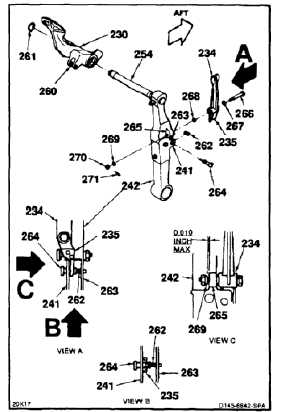
120.
Install pedal (230) on shaft (254), lug (260)
inward. Make sure it bottoms.
121.
Install retainer (261) on shaft (254). Use retaining
ring pliers.
122.
Position spring (262) between lugs (241 and 263)
of post (242).
123.
Install pin (264) in lug (241) and through spring
(262).
124.
Position lever (234) on aft side of lug (265) of
post (242) with channel (235) between lugs (241
and 263).
125.
Install bolt (266), three washers (267, 268, and
269), and nut (270). Tighten nut until lever does
not move forward or aft, but rotates freely. Back
off nut to align cotter pin hole.
126.
Check gap between washer (269) and lug (265).
Gap shall be 0.010 inch maximum.
127.
Install cotter pin (271).
128.
Repeat steps 107 thru 127 for left pedal (230).
INSPECT
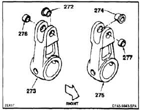
ASSEMBLE LEFT AND RIGHT OUTPUT ARMS
129.
Install bushing (dissimilar metals) (272) in right
lug of right output arm (273), flange inward.
130.
Install bushing (dissimilar metals) (274) in left lug
of left output arm (275), flange inward.
131.
Install bushing (dissimilar metals) (276) in left
lug of arm (273).
132.
Install bushing (dissimilar metals) (277) in right
lug of arm (275).
INSPECT
11-401