TM 55-1520-240-23-9
11-78
ASSEMBLE COPILOT’S COCKPIT CONTROL ASSEMBLY
(Continued)
11-78
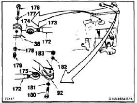
90.
If thrust connecting link (172) is a replacement,
loosen nut (173) of adjustable end. Turn bearing
(174) 90º to bearing (175). Torque nut to 100
inch-pounds.
91.
Position link (172) in bellcrank (38) upper arm,
fixed end toward bellcrank. Install bolt (176), two
washers (177 and 178), and nut (179). Do not
tighten nut at this time.
92.
Position link (172) in short arm of bellcrank (92).
Install bolt (180), two washers (181 and 182),
and nut (183). Do not tighten nut at this time.
Remove tag from link.
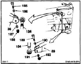
93.
Position thrust connecting link (184) in bellcrank
(38), fixed end toward bellcrank. Install bolt
(185), two washers (186 and 187), and nut (188).
Do not tighten nut at this time.
94.
Position link (184) in long arm of bellcrank (69).
Install bolt (189), two washers (190 and 191),
and nut (192). Do not tighten nut at this time.
Remove tag from link.
FLIGHT SAFETY PARTS
This is an installation critical flight
safety part. All aspects of its assembly
and installation must be ensured.
Ensure that both machined rod ends
attached to the link are secure.
Ensure that both rod end jam nuts are
installed and torqued.
Ensure that the rivet through the fixed
rod end bearing is secure.
Ensure painted band on control rod
faces towards pilot. (AFT)
Ensure rod end bearing faces aft
attaching to socket assembly.
At installation of this component,
ensure proper attaching hardware
(impedance type bolt, nut, and
washers) is installed including
verification of bolt head orientation,
torque, and installation of cotter pins.
Loose attachments within flight control
primary linkage will degrade aircraft
control. Missing components will
cause loss of control.
11-396