TM 55-1520-240-23-9
11-6
CHECK SERVOCYLINDER CONTROL VALVE FOR FRICTION
(Continued)
11-6
Do not disconnect control valve
connecting link. Damage to
servocylinder support structure or
swashplate can result.
NOTE
Procedure is same to check forward
or aft servocylinder control valves
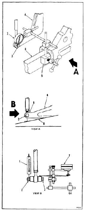
for friction. Check of forward left
servocylinder control valve is shown
here.
1.
Working from forward left work platform, attach
scale (1) to nut (2) of bolt (3) of forward left
bellcrank (4). Use twine (E433).
2.
Mount support (5) on structure (6). Position dial
indicator (7) on top surface (8) of bellcrank (4)
above bolt (3). Set indicator at mid-stroke.
3.
Pull scale (1) up until indicator (7) starts to read
or scale indicates 10 pounds. If indicator reads,
perform step 4. If indicator does not read, check
tunnel controls for binding (Task 11-6.1).
INSPECT
4.
Pull scale (1) down until indicator (7) starts to
read or scale indicates 10 pounds. If indicator
reads, perform step 5. If indicator does not read,
check tunnel controls for binding (Task 11-6.1).
INSPECT
5.
Perform control valve check on forward right and
aft servocylinder valves.
INSPECT
FOLLOW-ON MAINTENANCE:
Remove hydraulic power.
Remove electrical power.
Close forward and aft work platforms (Task 2-2).
END OF TASK
11-19


