TM 55-1520-240-23-9
11-57
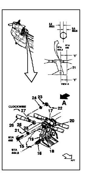
RIG AFT CABIN AND PYLON LINKAGE
(Continued)
11-57
4.
Working in aft tunnel section, check four bolts
(15, 16, 17, and 18) of aft idler bellcranks (19
and 20) at sta. 444.5. Measure and record
distance ‘Y’ between center of bolts and surface
(21) at sta. 440. Bolt centers must be parallel to
within 0.03 inch. If parallel, go to step 12. If not,
perform steps 5 thru 11, then go to step 12.
NOTE
Procedure is same to adjust position
of bellcranks (19 and 20). Bellcrank
(19) is shown here.
5.
Remove cotter pin (22), nut (23), two washers
(24 and 25), and bolt (15) from bellcrank (19).
Disconnect link (26) from bellcrank.
6.
Loosen nut (27) of link (26). Turn rod end (28)
clockwise to move bellcrank (19) forward.
NOTE
One half turn of rod end moves
bellcrank about 0.02 inch.
7.
Position link (26) in bellcrank (19). Install bolt
(15), two washers (25 and 24), and nut (23).
Tighten nut.
8.
Repeat step 4. If distance is same, go to step 9.
If not, repeat steps 5 thru 8.
9.
Torque nut (27) of link (26) to 103 inch-pounds.
10.
Torque nut (23) to 60 to 90 inch-pounds. Install
cotter pin (22).
11.
Check bolt (15). Bolt shall not rotate with torque
less than 10 inch-pounds. There shall be no
axial looseness. If bolt rotates or is loose, add
washer under nut and repeat step 10.
11-261