TM 55-1520-240-23-7
9-146.1
CHECK AND ADJUST POWER STEERING CONTROL BOX ON AIRCRAFT
(AVIM)
(Continued)
9-146.1
WIRING AND CIRCUIT CHECK
1.
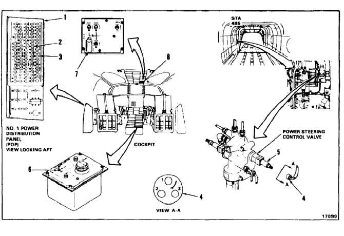
On No. 1 PDP (1), close (push in) BRAKES &
STEERING (2) and CAUTION PANEL (3) circuit
breakers.
2.
Disconnect connector (4) from valve (5).
3.
Set the LOCK-UNLOCK-STEER switch (6) to
LOCK.
4.
Apply external electric power (Task 1-37).
5.
Measure voltage between contacts 1 and 3 of
connector (4). There shall be bus voltage of
approximately 28 vdc.
6.
Measure voltage between contacts 2 and 3 of
connector (4). There shall be no voltage.
7.
Set LOCK-UNLOCK-STEER switch (6) to
UNLOCK.
8.
Measure voltage between contacts 1 and 3 of
connector (4). There shall be no voltage.
9.
On No. 1 PDP (1), open (pull out) BRAKES &
STEERING (2) circuit breaker.
10.
Connect connector (4) to valve (5).
11.
Set LOCK-UNLOCK-STEER switch (6) to
UNLOCK.
12.
On No. 1 PDP (1), close (push in) BRAKES &
STEERING (2) circuit breaker.
13.
Turn on BRK STEER switch (7) in overhead HYD
panel (8).
14.
Set LOCK-UNLOCK-STEER switch (6) to LOCK.
9-592


