TM 55-1520-240-23-7
9-145
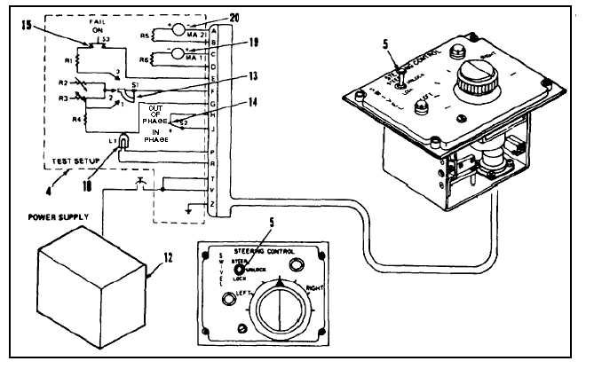
TEST AND ADJUST POWER STEERING CONTROL BOX (AVIM)
(Continued)
9-145
22.
Allow knob (6) to return slowly to neutral position.
Check motor (19 and 20).
a.
Meter (19) shall indicate less than 1 ma when
knob is about 45º.
b.
Meter (20) shall indicate 10 ma as the knob
passes the 45º position and remain at that
reading when the knob is at neutral.
23.
Set switch (13) to 2. Check meters (19 and 20).
Meters shall indicate between 0 and 1 ma.
24.
Set switch (15) to fail. Check lamp (18). Lamp
shall go out.
25.
Set switch (5) on control box to LOCK, then
STEER. Check lamp (18). Lamp shall come on
and stay on.
26.
Repeat steps 24 and 25.
27.
Set switch (14) to OUT OF PHASE, then to IN
PHASE. Check lamp (18). Lamp shall go out
and stay out.
28.
Repeat step 25.
29.
Repeat step 27.
30.
Repeat step 25.
INSPECT
31.
Shut down power supply (12).
32.
Disconnect test setup (4).
9-588