TM 55-1520-240-23-7
9-146.1
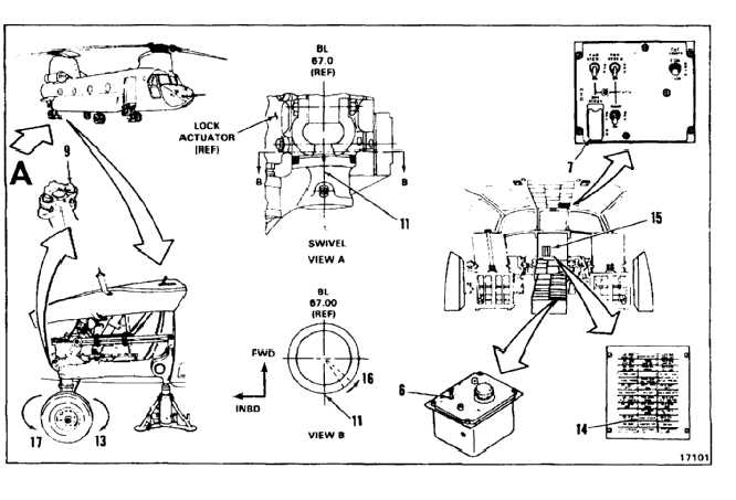
CHECK AND ADJUST POWER STEERING CONTROL BOX ON AIRCRAFT
(AVIM)
(Continued)
9-146.1
ELECTRICAL ZERO ADJUSTMENT
25.
Paint a thin vertical red line "N" (11) on the right
aft landing gear. Make line from 1/2 inch above
to 1/2 inch below swivel bushing shoulder.
26.
Set LOCK-UNLOCK-STEER switch (6) to
UNLOCK.
27.
Set BRK STEER switch (7) to OFF and set
LOCK-UNLOCK-STEER switch (6) to STEER.
28.
Manually swivel right aft wheel clockwise (13)
until the PWR STEER caution light (14) on
CAUTION PANEL (15) illuminates.
NOTE
Dimensions are measured from
neutral position on circumference of
swivel housing.
29.
Measure difference between line "N" on swivel
fork (16) and line "N" on housing (11) when
CAUTION PANEL (15) illuminates.
30.
Panel shall illuminate when line (16) is within
2-3/16 to 2-15/32 inches from line (11).
31.
Set BRK STEER switch (7) to ON and set
LOCK-UNLOCK-STEER switch (6) to LOCK.
a.
Check that wheel returns to within 1/4 inch
of lock position.
b.
Check that swivel lock (9) extends to lock
position.
32.
Set LOCK-UNLOCK-STEER switch (6) to
UNLOCK.
33.
Check that swivel lock (9) is unlocked.
34.
Set BRAKE STEER switch (7) to OFF and set
LOCK-UNLOCK-STEER switch (6) to STEER.
35.
Manually swivel right aft wheel counterclockwise
(17) until PWR STEER caution light (14) on
CAUTION PANEL (15) illuminates.
9-594