TM 55-1520-240-23-7
9-144
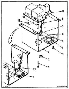
ASSEMBLE POWER STEERING CONTROL BOX (AVIM)
(Continued)
9-144
1.
Position connector (1) on frame (2). Install four
screws (3) and nuts (4).
2.
Position diode (5) and washer (6) on frame (2).
Install nut (7).
3.
Solder wire (8) to diode (5). Use solder (E360).
4.
Install five screws (9) and spacers (10) in frame
(2). Position plate assembly (11) on five screws
and spacers. Install five nuts (12) on screws (9).
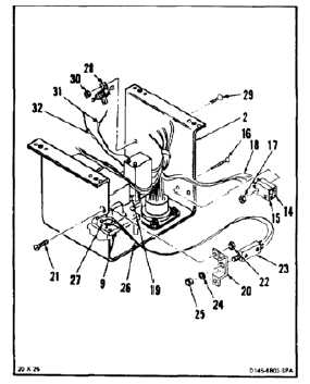
5.
Install 16 wires (13) in connector (1). Use contact
tool.
6.
Position two resistors (14 and 15) on side of
frame (2). Install two screws (16) and nuts (17).
7.
Solder six wires (18) to terminals (19) on plate
assembly (9). Use solder (E360). Remove tags.
8.
Position bracket (20) on frame (2). Install two
screws (21) and nuts (22).
9.
Position potentiometer (23) on bracket (20).
Install washer (24) and nut (25).
10.
Solder three wires (26) to terminals (27) on plate
assembly (9). Use solder (E360). Remove tags.
11.
Position resistor (28) on frame (2).
12.
Install two screws (29) and nuts (30).
13.
Solder two wires (31 and 32) to resistor. Use
solder (E360). Remove tags.
9-576