TM 55-1520-240-23-7
8-98
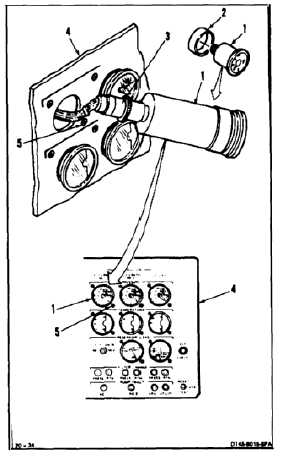
INSTALL CLAMP MOUNTED INSTRUMENTS IN MAINTENANCE PANEL
(Continued)
8-98
NOTE
Procedure is the same for installing
hydraulic pressure, temperature,
or reservoir level indicators in
maintenance panel. Installation of No.
1 Flight Control Hydraulic Pressure
Indicator is shown here.
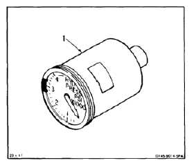
Be careful when handling indicators.
Rough handling will damage
indicators.
1.
Clean bonding surface of indicator (1). Use cloth
(E120).
2.
Check indicator (1) for range marks. Apply range
marks and index mark to indicator if required (TM
55-1520-240-10 and TM 55-6600-200-20).
3.
Install spacer (2) on indicator (1).
4.
Connect wire harness connector (3) to indicator
(1).
5.
Install indicator (1) in maintenance panel (4).
6.
Tighten round head clamp screw (5).
7.
Apply index mark, if required, from maintenance
panel (3) to indicator (1) (TM 55-6600-200-20).
INSPECT
FOLLOW-ON MAINTENANCE:
Perform operational check of affected system (TM
55-1520-240-T).
END OF TASK
8-307