TM 55-1520-240-23-6
7-159
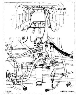
INSTALL PRESSURE CONTROL MODULE FILTER INDICATOR
7-159
INITIAL SETUP
Applicable Configurations:
All
Tools:
Aircraft Mechanic’s Tool Kit, NSN 5180-00-323-4692
Torque Wrench, 0 to 150 Inch-Pounds
Materials:
Cloths (E135)
Lockwire (E231)
Parts:
Preformed Packings
Retainer
Personnel Required:
Medium Helicopter Repairer
Inspector
References:
TM 55-1520-240-23P
1.
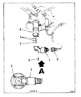
Position indicator (1), retainer (2), and two
packings (3) in FILTER bowl (4). Use cloths
(E135) for spilled fluid.
2.
Lubricate and install four screws (5) in indicator
(1). Torque screws to 33 inch-pounds in
diagonal sequence. Lockwire screws. Use
lockwire (E231).
Electrical connectors are to be
tightened no more than 1/16 to
1/8 turn beyond finger-tight during
installation, otherwise they will be
damaged.
3.
Connect connector (6) to indicator (1).
INSPECT
FOLLOW-ON MAINTENANCE:
Perform operational check (TM 55-1520-240-T).
Bleed utility hydraulic reservoir (Task 7-335).
END OF TASK
7-686