TM 55-1520-240-23-6
7-135
UTILITY HYDRAULIC SYSTEM
(Continued)
7-135
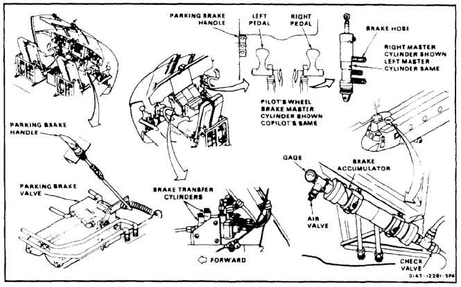
Wheel Brake System Description
The helicopter is fitted with a power-assisted
self-adjusting disk brake assembly at each of the four
forward and two aft wheels.
NO BREAK - WORK HARDER
The pilot and copilot each have two brake pedals,
mounted on the toe of the yaw pedals. The left and right
pedals operate the brakes on the corresponding side of
the helicopter. Braking on all wheels is obtained when
either pilot or copilot presses both pedals.
NO BREAK - WORK HARDER
Each pedal operates its own master cylinder with its
own pressure supply. Transfer valves in the left and
right system combine pilot and copilot brake input to the
corresponding brakes.
NO BREAK - WORK HARDER
A parking brake valve allows the brakes to be set and
held on by keeping the lines between the valve and the
brakes pressurized. The valve is actuated by a cockpit
parking brake handle. When the handle is pulled out, a
light on the master caution panel comes on to warn that
the brakes are on.
NO BREAK - WORK HARDER
The brake master cylinders are at the base of their
corresponding brake (yaw) pedals. The transfer valves
and the parking brake valve are located in the nose
compartment. An accumulator in the forward fairing left
of the forward transmission maintains system pressure.
It has enough reserve to allow several power-assisted
stops if system pressure is cut off. In case of a failure in
the utility hydraulic system, the wheel brake system can
be isolated from the failure by closing a solenoid valve
in the pressure control module. The valve is closed by
a switch on the overhead HYDRAULIC panel in the
cockpit.
7-620