TM 55-1520-240-23-6
7-102
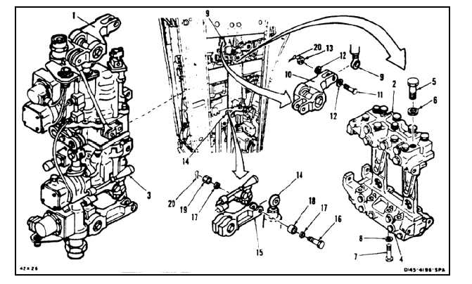
INSTALL INTEGRATED LOWER CONTROL ACTUATOR (ILCA)
(Continued)
7-102
NOTE
Procedure is same to install any
integrated lower control actuator
(ILCA) except where noted in text.
Installation of pitch actuator is shown
here.
There are no electrical connectors on
thrust actuator.
1.
Have helper support actuator (1). Position
actuator on manifold (2). Align tube (3) with port
(4).
NOTE
There are four bolts installed in
actuator. Two on top and two on
bottom. Top bolts are longer.
2.
Install two bolts (5) and washers (6).
3.
Install two bolts (7) and washers (8).
4.
Torque bolts (5 and 7) to 60 inch-pounds.
5.
Lockwire bolts (5 and 7) in pairs. Use lockwire
(E231).
6.
Position rod end (9) in lever (10). Install bolt (11),
two washers (12), and nut (13).
7.
Position rod (14) in lever (15). On pitch actuator
(1), install bolt (16), two washers (17), bushing
(18), and nut (19). On roll, yaw, and thrust
actuator (1), install bolt, three washers, nut, and
cotter pin.
8.
Torque nuts (13 and 19) to 30 to 60 inch-pounds.
9.
Install cotter pin (20) in nuts (13 and 19).
10.
Check bolts (11 and 16). Bolts shall not rotate
with torque less than 10 inch-pounds. There
shall be no axial looseness. If bolts rotate or are
loose, add washer under nut (13 and 19) and
repeat steps 8 and 9.
INSPECT
7-486