TM 55-1520-240-23-6
7-4.2
TUBE BENDING (AVIM)
(Continued)
7-4.2
9.1.
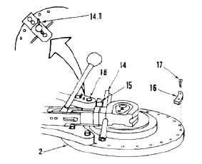
Check that control lever (14.1) is set to the right,
as shown.
10.
Adjust operating arm forming nose (15) against
follow-block (14).
NOTE
The distance between two holes in
the base is equal to 12.5º.
11.
Position angle stop (16) on base (2) at correct
position to obtain desired bend (DIAL H DEG
BEND Column of Chart B). Allow for springback.
Install two bolts (17).
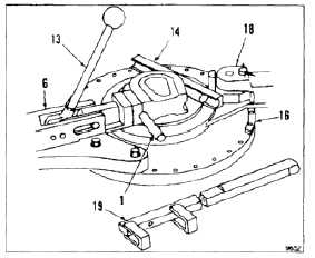
12.
Advance operating arm (18) with steady pressure
until angle stop (16) is met. Use extension arm
(19) with operating arm (18) if additional leverage
is required.
13.
Return operating arm (18) to starting position
and remove follow-block (14).
14.
Release lock handle (13) on quick-lok clamp (6)
and remove tube (1).
15.
Repeat steps 8 thru 14 for all required bends in
tube (1).
7-25