TM 55-1520-240-23-6
7-32
INSTALL NO. 2 POWER CONTROL MODULE
(Continued)
7-32
3.
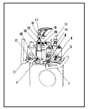
Connect tube (5) to port (6). Remove tag.
4.
Connect tube (7) to SYS RTNCV port (8).
Remove tag.
5.
Connect tube (9) to port (10). Remove tag.
6.
Connect tube (11) to port (12). Remove tag.
7.
Connect tube (13) to port (14). Remove tag.
8.
Connect connector (15) to PRESS XMTR
receptacle (16). Remove tag.
9.
Connect connector (17) to SYSPLTV receptacle
(18). Remove tag.
10.
Connect connector (19) to SYS PRESS SW
receptacle (20). Remove tag.
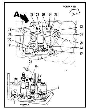
11.
Connect connector (21) to switch (22). Remove
tag.
12.
Connect connector (23) to switch (24). Remove
tag.
13.
Connect tube (25) to RSVR RTN port (26).
Remove tag.
14.
Connect tube (27) to SYS RET port (28).
Remove tag.
15.
Connect tube (29) to port (30). Remove tag.
16.
Connect tube (31) to port (32). Remove tag.
17.
Connect tube (33) to PTU PRESS port (34).
Remove tag.
18.
Connect connector (35) to FLT PUMP FAIL
indicator (36). Remove tag.
19.
Tighten three bolts (3).
INSPECT
NO BREAK - WORK HARDER
NO BREAK - WORK HARDER
FOLLOW-ON MAINTENANCE:
Bleed flight control hydraulic system (Task 7-16).
Service flight control accumulator (Task 1-63).
Service flight control reservoir (Task 1-61).
Perform operational check (TM 55-1520240-T).
Install left and right access covers (Task 2-2).
END OF TASK
7-182